
Ensuring the safety of personnel and safeguarding electronic equipment against earth faults, lightning strikes, electrical surges, and electromagnetic impulses is paramount at any communication site. While it’s impossible to entirely prevent unforeseen electrical occurrences such as lightning strikes and power surges, this guideline offers valuable installation insights into external earthing electrode systems. These systems play a crucial role in mitigating damage caused by such events. Moreover, in instances of unusual site conditions, extra effort may be necessary to achieve a securely bonded and earthed site.
Earthing Systems: Understanding the Basics
System Earthing: This involves intentionally connecting a point in the standard electrical circuit to the earth.
Protective Earthing: This refers to earthing conductive components not part of the regular electrical circuit to shield individuals from dangerous touch voltages during an earth fault occurrence.
Essential Qualities of a Good Earth Connection:
- Low electrical resistance to the earth
- High corrosion resistance
- Capability to handle required fault current repeatedly
- Reliable lifespan of at least 20 years
Key Factors Influencing Earth Electrode Resistance:
- Soil resistivity
- Electrode dimensions
- Available earthing area
- Earth electrode material
- Contact resistance of electrode and earth
Purpose of Earthing and Bonding Systems:
- Facilitate rapid detection and disconnection of faulty equipment and circuits during short circuits to earth.
- Reduce risks to personnel and equipment from earth faults on electrical equipment.
- Shield against lightning and static discharges.
- Mitigate adverse effects of electromagnetic interference in instrumentation and control systems.
- Limit voltage caused by accidental contact of the site AC supply conductors with higher voltage conductors.
- Dissipate electrical surges and faults to minimize injury from earthing system potential differences.
- Stabilize AC voltage under normal conditions relative to the earth.
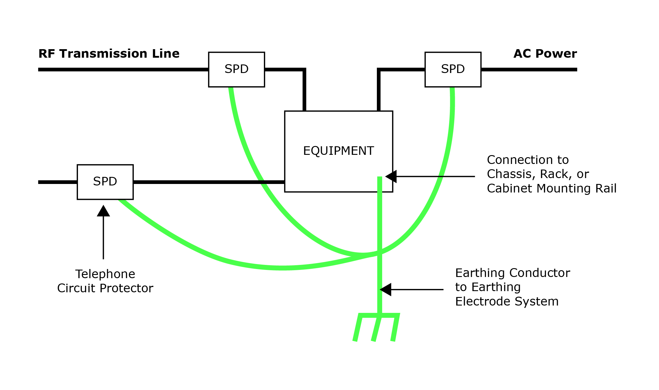
- Assist in the operation of surge suppressor units.
- Provide a common signal reference earth.
A communication earthing system is made up of two sub systems – External and Internal. These consist of certain basic components arranged to achieve the goals of the earthing system and adapted to the characteristics of each individual site.
Components of Earthing Electrode System:
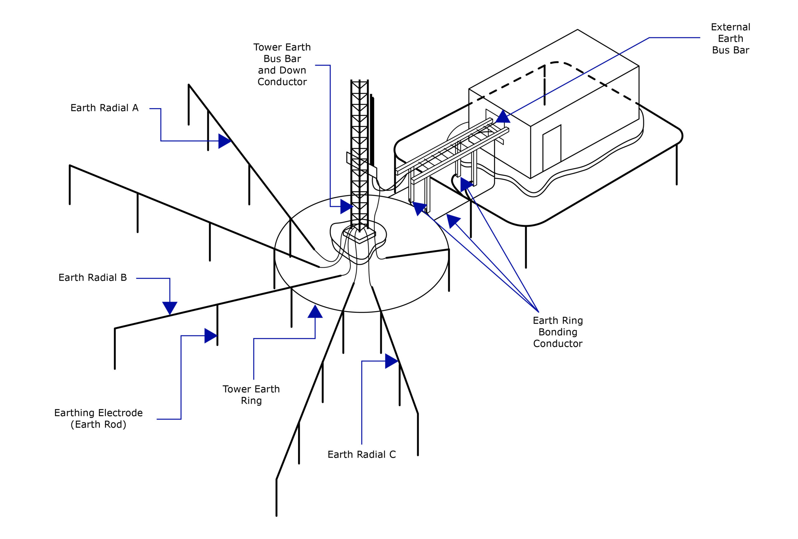
The External earthing system will consist of the following components:
- Electrolytic Earthing Electrodes
- Earth Enhancing Material
- Earthing Conductor
- RF Cable Shield Earth Kit
- Tower Earth Bus Bar
- External Earth Bus Bar
- External Earth Ring
- Earth Radials Kit
- Guy Wire Earthing Conductor Kit
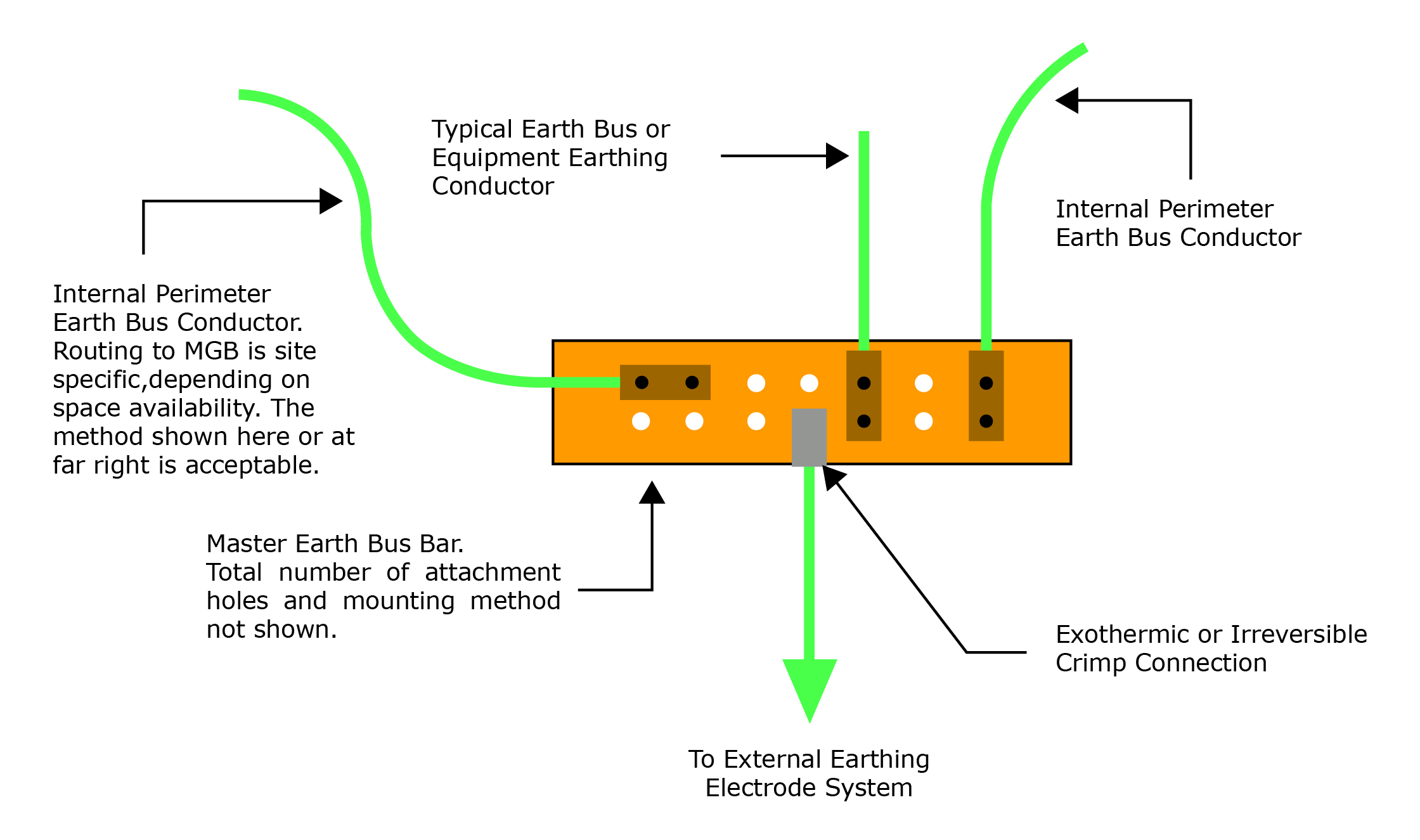
The Internal earthing system must have a low impedance path to earth and achieve a minimal potential difference between conductive structures within the site, while eliminating or at least minimizing) any surge current flow through the site equipment. Safety of personnel and equipment is the overriding concern and not the signal earth. The Internal earthing system consists of:
- Master Earth Bar
- Internal Earth Ring
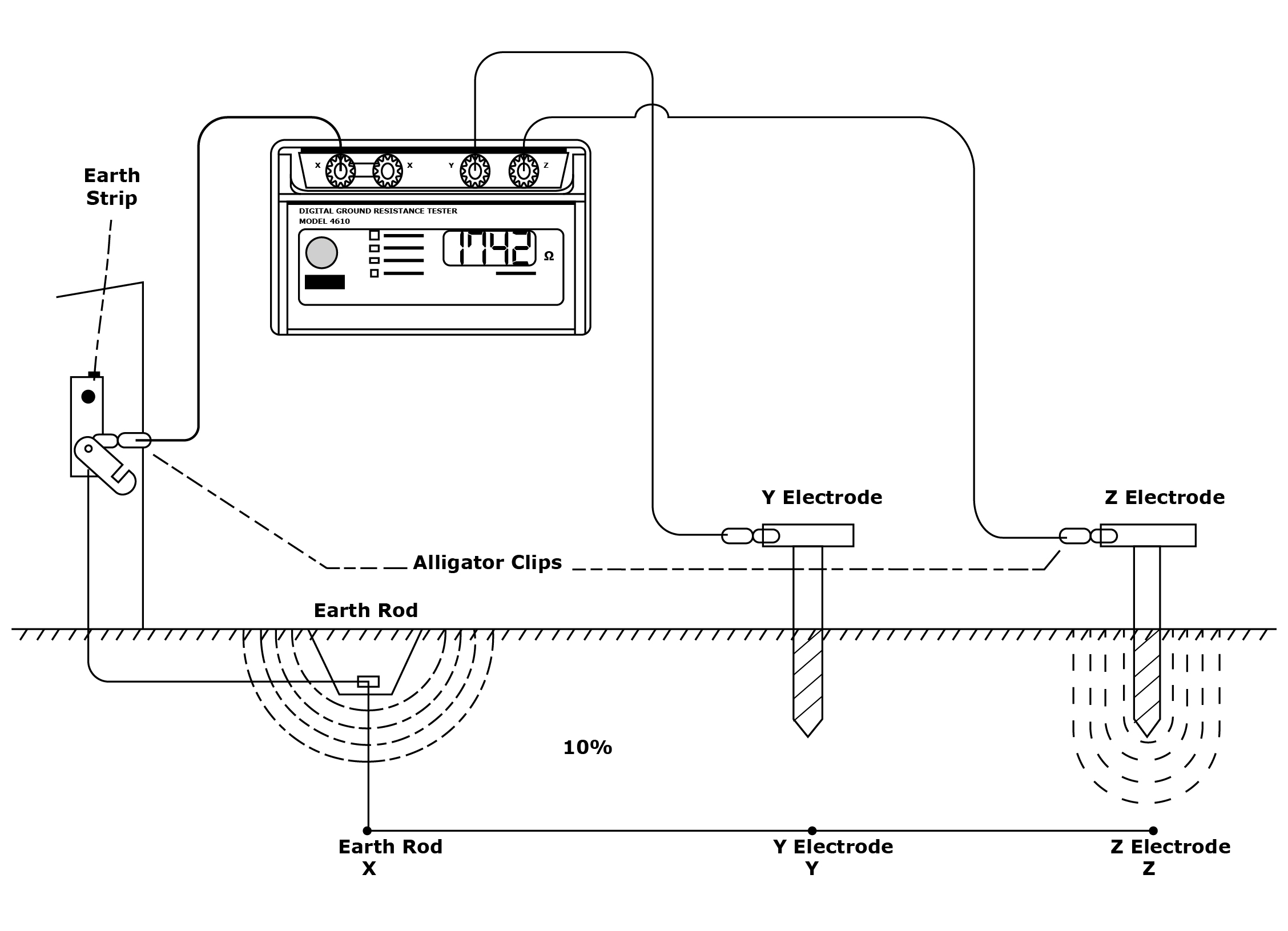
Earthing System Testing:
The resistance of an earthing electrode system must be measured post-installation and prior to bonding it with the power company neutral wire or any other utility. Testing should also occur if there’s suspicion of a direct lightning strike.
Electrolytic Earthing System:
Many communication companies utilize LYTECH’s Electrolytic Earthing Systems for earthing their communication equipment and facilities. Typical applications include cellular tower structures, earth antennas, rooftop installations, and telecom buildings/shelters. LYTECH’s EES systems boast simple, cost-effective installation, low maintenance, and stable extended service. Contact us today to learn more or receive a quotation.