
A properly designed ground system is an integral part of a site and should be regarded as highly as all of the other equipment critical components.
We all have become dependent on electronics for our everyday lives. These same sensitive devices are very vulnerable to the hazards created by poor grounding. As any power quality expert will relate, poor grounding is second only to improper wiring as the leading cause of equipment malfunction. Standards for equipment performance mandate the installation and maintenance of a reliable, low resistance earth ground. These standards often cannot be met and certainly cannot be assured for the long term by traditional grounding methods, which call for minimum requirements.
Much of this equipment operates on 5V or less and is often subjected to higher steady-state transients. A properly designed low resistance system can ensure the operation of critical equipment that often creates its own hazards, such as harmonics and transients. An additional benefit also comes in enhanced personnel safety.
Earth Grounding
The definition of a ground electrode is “a conductor or group of conductors in intimate contact with the earth for the purpose of providing a connection with the soil.” This definition does not refer to an actual ohm resistance value of the electrode. The resistance value is determined by the resistivity of soil with which these electrodes are in contact. As in the case of ground water, the current must pass through the soil to the assumed earth potential of 0 Ω.
When an object is grounded, it is then forced to assume the same zero potential as the earth. If the potential of the grounded object is higher or lower, current will pass through the grounding connection until the potential of the object and earth are the same. The earth electrode is that connection path from the equipment to the earth (Figure 1).

The resistance of the electrode, measured in ohms, determines how quickly and at what potential energy is equalized. Hence, grounding is necessary to maintain an object’s potential equal to that of the earth’s.
Soil Resistivity
The soil is the dynamic conductor for steady state, natural, and man made fault currents. Most soils naturally contain varying amounts of electrolytes that conduct electricity. As a result, the addition of moisture will enhance or reduce the conductive properties. In general, however, the greater the moisture contents in soil, the lower the resistivity. Temperature, like moisture, can have a significant impact on resistivity.
Soil resistivity varies with temperature, especially when reaching 32°F (the moisture in the soil freezes and the resistivity increases by almost three times its unfrozen value). This can have a detrimental effect on your clay or cement-based backfill materials that rely on water as their primary conductor. A carbon-based backfill material will have the advantage of being an all weather, year round, low resistance conductor.
Soil Resistivity Measurements
To determine the conductivity of the soil, a four-point ground meter is utilized (Figure 2).
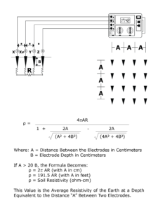
This test requires the user to place four equally spaced auxiliary probes into the earth to determine the actual soil resistance, traditionally in ohms cm. This test must take place around the entire area to determine the soil value at all locations.
This test is done at different spacing, 5 to 40 feet, to determine the resistance value at various depths. This knowledge will aid in the design and implementation of the correct ground system to meet the particular site requirements. Soil values can range from 500 Ω cm with large amounts of electrolytes to over 1 million Ω cm in sandy dry soil.
Post Installation Testing
Once a ground system has been designed and installed, the verification process begins. This requires the use of a three point, fall of potential, ground resistance method (Figure 3).

This test involves the use of two auxiliary probes placed in the ground in a straight line. The lengths of the conductors from the instrument to these probes are determined by the size of the facility under test. This is traditionally five times the diagonal distance of the grounding system. The test must also be performed before tying into any other ground source. The reason for this is to verify that your system has the designed ground resistance value without influence from outside sources.
If the test is performed after the power is connected, the clamp on ground-resistance tester can be utilized (Figure 4).

This involves clamping onto the power neutral between the utility transformer and the site ground. The user must be aware that a 0.7 Ω reading indicates a continuity loop and not ground resistance.
Low Resistance Grounding System Design
The design process for a grounding system begins with a site and power survey of the installation area (Figure 5).
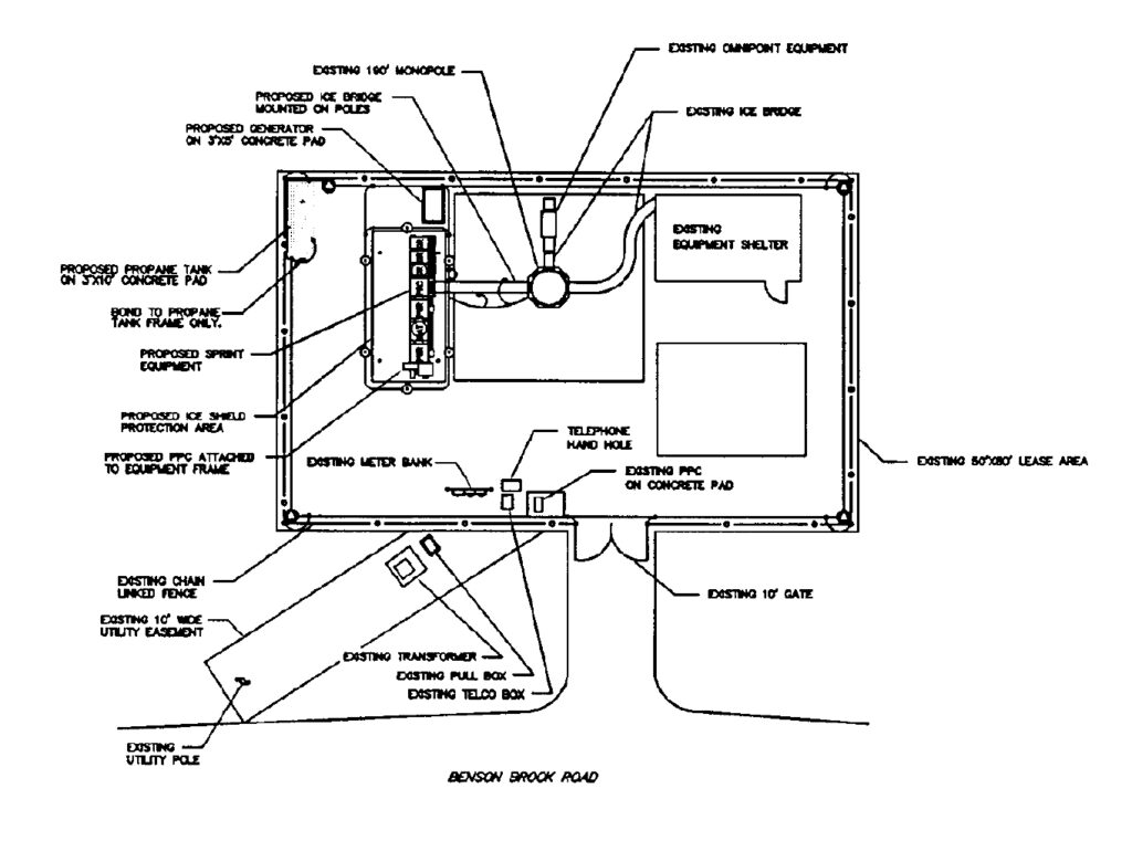
The power survey includes bonding and grounding methods of present ac, telecommunications, TVSS, UPS, and many other systems that operate the facility. A site survey must also include soil resistivity analysis at several depths, relevant site plans, topography analysis, and a boring core sample, if available. The site survey will show if any physical barriers such as rock, high resistivity soil, or power lines will affect the earth ground resistance in the installation area. Once this information is obtained, an effective design can be initiated.
Benefits of a Well Designed System
A properly designed low resistance grounding system will play a major role in obtaining and maintaining a well-protected and efficient facility. This may be achieved with traditional methods and/or an enhanced system with electrolytic electrodes with carbon backfill. The ground system is an integral part of the site and should be regarded as highly as all the other equipment critical components.